• Protip: Profile posts are public! Use Conversations to message other members privately. Everyone can see the content of a profile post.

bogle's 1991 mild build thread

Coolant overflow tank

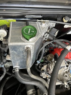
My car came with an aluminum coolant tank / catch can combo: (if anyone knows who made it plz chime in… Dali? It’s also for sale)

9DB2772A-538D-4B10-BA6A-5CF8CEA400EA.jpeg

I’m going for a more OEM+ look in the engine bay, though. Also the aluminum one doesn’t have a sight glass for coolant level. I figured I’d move to an OEM tank with R condom, so into the amayama cart it went.

24591A95-9F98-488E-AC36-4282029E4643.jpeg

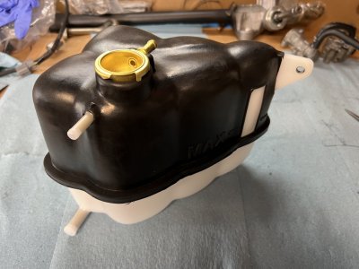
The cover stretched over the tank

6CD6C9EC-A8BA-4E65-9006-D361E9935A1D.jpeg

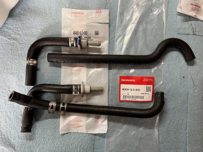
The brake booster lines were really old, I even had to slice the one at the TB to remove it from the TB nipple. I guess I’m restoring this car now, so all new lines. The TB line seems like a newer model one, but it looks like it’ll work:

8E6FBB3B-B720-45E0-898B-F5DCD5089946.jpeg

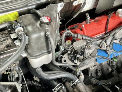
And all together. Everything is new here, lines, bracket, bolts, cap. Feels good

D472E777-CF40-48EB-8D4F-99CEE5760D2E.jpeg

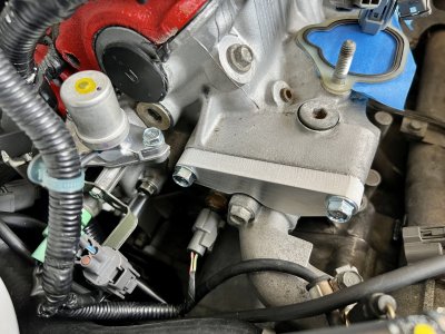
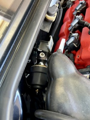
An on to the install. One little snag was my oil pressure sensor block being in the way. There was more room behind the aluminum tank, and the dash gauge pressure sender doesn’t fit

5812169F-0170-46E5-ABF4-F2055933DA93.jpeg

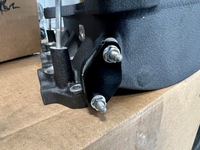
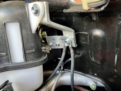
I had a bunch of complicated ideas, but in the end I was able to just reverse mount the thing and modify the bracket a bit.

6E6FFB14-2B47-4C78-BA91-0ADD84A64012.jpeg

Now the oil sensor bits are pretty tucked in there. The sensor touches the tank, but it’s fine

78B91964-7F83-4F30-9B02-76D5C5C85D9F.jpeg

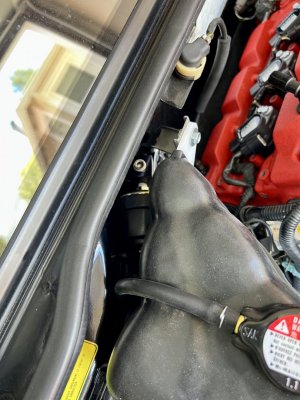
Done! New OEM vibes! You can see a bit of the sos catch can in the corner of the pic too.

0903D959-770D-4C68-88FB-235785A02839.jpeg
 
The brake booster lines were really old, I even had to slice the one at the TB to remove it from the TB nipple. I guess I’m restoring this car now, so all new lines. The TB line seems like a newer model one, but it looks like it’ll work:

View attachment 179752

And all together. Everything is new here, lines, bracket, bolts, cap. Feels good

View attachment 179753
Nice job. This is the ONE part on the engine I didn't replace. I wonder if mine looks like that...
 
Thanks! The booster hoses were super ugly and the ends were brittle. Also the check valve was ashy from a lot of sun exposure, the bolts were dirty, and the bracket was all oxidized. Cleaning this little stuff up gives the ol’ OCD a little satisfaction
 
Intake manifold stuff

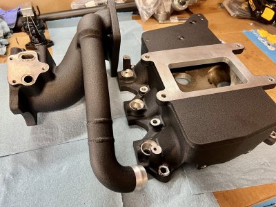
I took the intake manifold and inlet snout to a local shop to have the supercharger bypass pipe extended and fresh wrinkle black powder coat. You can see the long pipe has 2 new welds on it around a 1” extension:

78AA9E0E-8245-46B2-887F-2A357613A1C4.jpeg

The pipe needed to be extended because the new phenolic plate will raise the supercharger up by an inch. This is what it looked like before the extension, no fit:

96640A14-8D8E-4E41-82D0-5238B72DDF25.jpeg

Probably doesn’t make sense, but I’ll do a whole post on the phenolic plate once everything is installed. It forced me to make a lot of changes.

Before the powder coat, there were tons of chips, bare bits, and weird painted parts of the manifold and inlet. This pic doesn’t really sell it, but it was a mess, man:

18C9F187-0CAE-4B10-90C4-B8339F74797E.jpeg

The shop

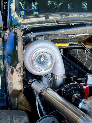
The shop that did the work was Chuckles garage. If you follow hoonigain related stuff, you’ll probably know his truck: old smokey. It’s a crazy 50’s ford F1 that makes like 1200 or 1500hp and holds the diesel pikes peak record. It was awesome to see this thing in person:

1B24BBCC-74CE-4C4B-9CAE-4165D120A581.jpeg

This is without question the biggest turbo I’ve ever seen. It’s probably around 1 foot in diameter, and uh, it’s feeding another giant turbo. Deep sympathy for any local small birds…

D32E3837-1541-4ABF-94FD-3DD880A216FD.jpeg

Scott, the main guy was super nice. I was surprised he was willing to take on my dumb little project. I grew up around fabricators, my dad has a fab shop, all his buddies had hot rod shops. They were gruff dudes, annoyed anytime a rando showed up with a tiny project and opinions on how to do it. Clueless guys were sent packing all the time.

I was the rando and I was expecting gruff annoyance, but he chatted with me, showed me all the crazy cars at the shop, and gave me suggestions on how to do some water meth things. Best thing is that he did a perfect job with the parts. Super positive experience all around. He has a dyno and an expert haltech tuner too, so another visit is probably in order. Someday I’ll get that haltech…
 
EACV and fast idle valve

One great thing about tearing the car down for the supercharger rebuild is the opportunity to inspect and clean everything. I’ve cleaned, replaced, and now know the status of a whole bunch of parts I wouldn’t otherwise have messed with.

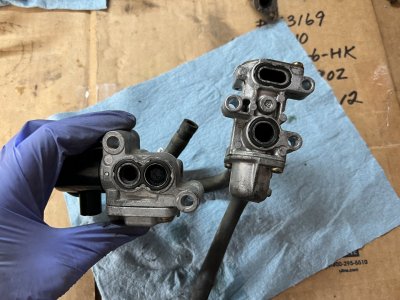
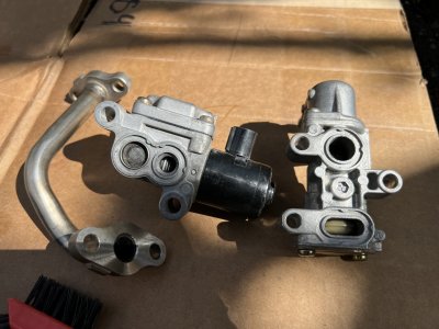
The fast idle valve and EACV fall into that don’t care category, but here we are. They were way dirty, probably never been cleaned in all their 135k miles. Here they are off the car:

346E0408-526D-4569-8650-3CB21E9B279F.jpeg

First step was a load of carb cleaner and a brass brush. They cleaned up pretty ok:

7FD5E447-BDD5-437A-A815-F143807CB4D5.jpeg

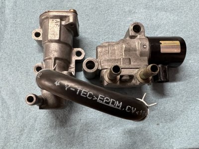
New hoses on there, V-TEC, yo:

51C01C3B-7999-484A-989A-C710C2E48D28.jpeg

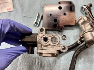
IACV/EACV screen replaced. This was harder than expected. It’s kinda pressed in there. I kinda mangled the old one with the pliers, then pressed the new one in by bolting up the IACV without the o rings.

D68F9974-BBFB-4898-859D-995EA7329D88.jpeg

The plate in the background above is a manifold sandwich plate. It looks like the newer cars don’t have an IACV? The snout only has provision for the fast idle valve, then the plate is an adapter to bolt up both bits. Because of the plate, I needed 2 sets of fast idle valve o-rings!

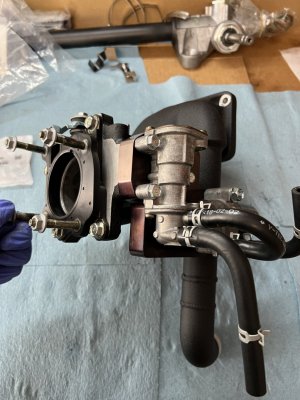
All assembled on the intake snout:

7C4C3F64-4CA9-40F5-BD7E-ABBCA20D73FC.jpeg

All new bolts and nuts here. The CTSC hardware on my car was all hardware store junk, every crappy bolt I could find got a new Honda replacement.

FWIW I got a lot of mileage out of the 95701-0X0XX08 bolt part number. It’s a zinc plated bolt without a washer in both M6 and M8 at a bunch of different lengths. The first X is the diameter (6 or 8), then the second XX is the length in mm. For example the shiny fast idle valve bolts in the pic above are 95701-0604508, 45mm M6 bolts with a 10mm head
 
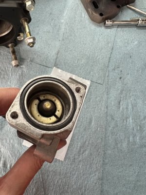
I tightened the fast idle valve donut today, it was pretty loose! I spun this tighter with my fingers:

1FD8DD63-322B-4EF4-92DE-5B60BE591D6D.jpeg

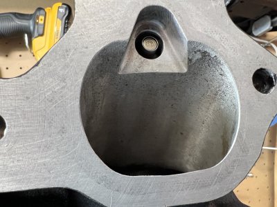
And then this is what the donut looks like through the top port when tight. Mine was higher by like 1/4” before tightening. New gasket in the background

DDE1CB74-95A8-4A79-BC1E-2F8D9676AA9A.jpeg
 
Injector reinstall

I’m still waiting on the supercharger rebuild to be finished. They’ve had it for a while now; not ideal, but it gives me some space to take my time carefully putting things back together.

I installed the injectors over the weekend. They turned out to be a bit of a saga, but they are sorted now and I have a plan for the future.

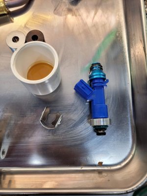
I got a set of EV14 550s (thanks @RYU!) to replace the RC 550s:
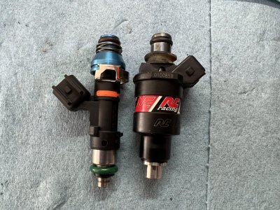
D0792326-41F9-4068-A0FF-45BE0E472C60.jpeg

I was originally planning on installing the EV14s now since everything is already apart, but ultimately decided to stick with the RCs in the near term. Even though they are the same size, the new injectors almost certainly will require some part of the fuel map to be retuned. I’m replacing a whole bunch of parts in this pass, moving the WMI nozzle, etc., if one of those things makes it run differently, it’ll be hard to tease apart issues from some replaced part and the new injectors. Like what if it’s hard to start? Is it the injectors or messed up vacuum routing?

The plan is to get it running the same or better than before with the RCs, then do the EV14s on their own and retune parts of the map with the injectors as the only variable.

Problem?

The RCs were already in the car! Reinstalling should be straightforward! Haha nope, lol aftermarket parts…

When I went to remove the rails, the rear rail bolts were straight up loose. Like loose loose, hardly hand tight. I could move the rail around with pretty minimal pressure. Yikes.

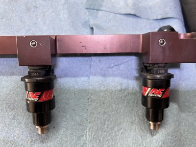
I initially thought, well it just needs to be tightened, eh? Turns out tightening the rail bolts forced the injector so far into the rail that it over-squished the grommet and made the harness plugs not fit on the injectors. My guess is that someone _intentionally_ left the rails kinda loose so the plugs would fit. Derp. Seems like a fire waiting to happen.

Here are the grommets over-squished:
60C073DE-7345-48C1-BCF6-6F40CACF3E2A.jpeg

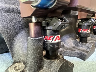
With no tension on the rail bolts, there was like a 1/4” between the rail and the stand-off, even with over-squished grommets:
14F6D7E0-6717-46DF-8724-8FFFE690291F.jpeg

The tl;dr is that either the injectors were too high, or the rail standoffs were too short.

On the manifold side, there is a rubber seal:
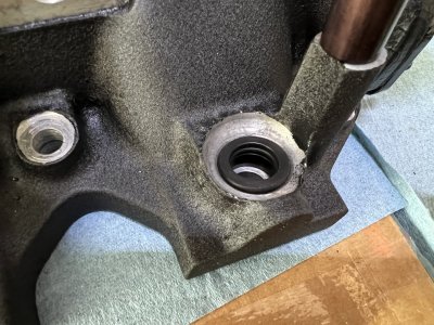
93578FCD-E237-4B7C-B4C6-21AB8E290498.jpeg

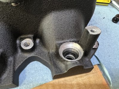
On my car, there was a 6mm aluminum riser under each seal. For reference here is the manifold seal without the riser:
D82FE670-EF01-4365-815F-FA03F6D2E929.jpeg

Lower, eh? At first I thought this riser was necessary for some reason, maybe injector to manifold interference? After some tinkering I realized the riser was probably not at all necessary and without, the injector seems to be better positioned within the manifold.

With the riser, the injector is tucked far back into the manifold. These injectors must have a pretty narrow spray pattern…
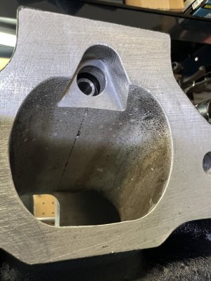
CBBE80BF-73E5-4BB1-A138-5D369CD16755.jpeg

Then without, the tip is much more flush. Possibly better for atomization cause fuel won’t gather on the manifold edges? Idk.

8FB1FC48-BCDF-4403-93E5-4718435798C6.jpeg

Install

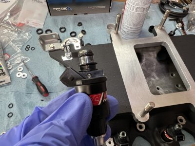
With that sorted out, I could install them. The injectors got new o-rings, grommets, and a little silicone grease:
EE44EE85-6FD1-4DFE-9922-F3F5B9949B98.jpeg

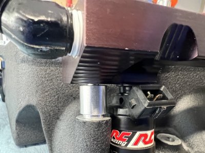
The old standoffs were about 15.5mm tall and would probably have worked, but they put almost no tension on the grommet/injector which made me nervous. I wanted a tight seal on the lower grommet, so here it is with a 1/2” standoff plus a 2mm spacer: 14.7mm tall, about 1mm of space to put more tension on the injector when tight:
B632773C-B40D-48C7-9271-E293C06714FF.jpeg

All tight now, it feels like just the right amount of grommet squish, tension on each injector, and plenty of room for the injector plug:
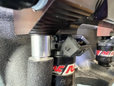
46747B20-AEC6-4A11-802C-EBF686464CF0.jpeg

Any CTSC people out there know why there was a riser on the injectors in the first place?
 
I remember going through a few different iterations of the fuel rails like you did, but I've only tried them on OEM injectors and RDX. Don't recall those aluminum risers at all and I ended up not using the black rubber donuts with the RDX. Sorry, I can't be of more help. I skipped the RCE injectors.
 
I mean thanks for the new injectors, they will be a big help long term!

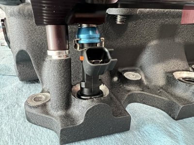
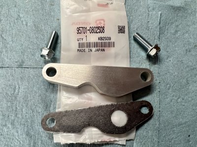
Every injector seems like it has its own mounting nonsense. I have all the parts for the EV14s now, they required no rubber donuts, these little adapters at the manifold, and 5mm taller rail standoffs:

087185DF-64B5-4AA2-9B26-31E6222E8DAB.jpeg

Looking forward to proper atomization! The EV14s seem like they’ll do a better job…

F562A75E-9BFB-4209-9D5C-C1A5E5CE167F.jpeg
 
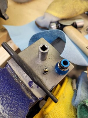
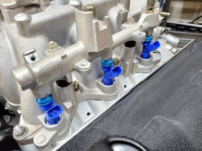
This may help with the EV14 fitment. I believe they are the same form factor as the RDX. I noticed you are using the same blue rail adapters as me. On the RDX injectors, I discovered the integrated filter on the adapter interfered with the filter on the injector- the adapter would not seat all the way down onto the injector hat. I had to punch them out.

20211008_124942.jpg

Also, I used aluminum spacers to securely seat the injector into the manifold. I did not use the rubber rings. By drilling out the manifold with Brad's kit, the green O-ring seals directly onto the manifold. I feel this is a much, much safer fitment than sealing against the rubber ring, which then seals against the manifold. Fire bad. :)

20211008_123537.jpg

Finally, I found that using the OEM phenolic spacers gave the best fitment in terms of snugness. Brad included a set of aluminum spacers with his RDX kit, but I didn't really notice a difference and I prefer the phenolic to keep some heat off of the rails.

20211008_135251.jpg
If the EV14 are the same size as the RDX, this should work for you too.
 
If I was in your shoes, i'd skip the RCE injectors all together. You can tune w/o the water/meth and just use it strictly for intake charge temp cooling (i.e. don't add timing). That's a win win for safety IMO.
Yeah I totally get this. Part of me really wants to just use the EV14s now. But the car is already tuned for the RCs and I just want to minimize disruption. I’m not planning on tuning more with the RCs unless it runs way different for some reason.

Definitely not going to be adding timing for water meth, but I do want to try adding some meth in there for an octane boost and see how it affects afrs with the new nozzle placement and smaller nozzle. I’d do a little of that with the RCs cause I have so much data on the old placement water-only with the RCs
 
This may help with the EV14 fitment….

Thanks for this. I had no idea the RDX injectors were the same form factor. I’ll def look into the top filter and make sure it seats. RYU added the blue adapters and ran them in his car so maybe ok?

Also good to know you ended up drilling out the manifold to have the o ring seat there.

Did you make the aluminum rings above the lower o ring? How far does the injector nozzle protrude into the intake stream? I guess the deeper the better eh? I like the idea of the phenolic standoffs, do you know how tall they are?

For the lower adapters, I ended up with these b series ev14 adapters:


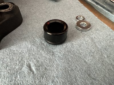
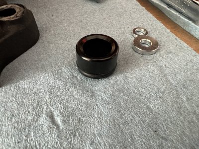
I emailed him and he made me a pack of 6. They are aluminum and have an outer o ring to seal against the manifold, then the injector bottom o ring seals the inner. The black thing here:

1C6DE3E7-4CC5-436F-9EA3-4491695BD202.jpeg

Dimensions are 21mm OD x 14mm ID and 18mm tall

I mocked up the new injectors to get a sense for stand-off height (20mm was right)

BD072C78-71A0-4087-A5F2-8FF44592C6FA.jpeg

It looks like yours are probably 1/4” deeper into the manifold if the lower o ring is seating on the manifold itself
 
Supercharger rebuilt!

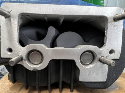
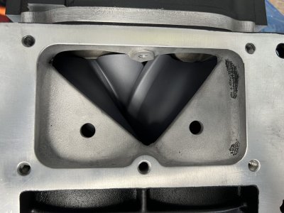
I got the supercharger back from the rebuilder (Jon Bond performance) and it looks fantastic:

2436BC0D-8CFC-4605-83A1-4621615E9EB4.jpeg

The inlet, rotors are ceramic coated:

3D85092A-03A6-40AE-9C52-3ECC63674838.jpeg

The outlet:

ABE9DA62-EE26-4B16-9D8E-2DA9A27A1CE0.jpeg

Almost everything inside has been replaced or upgraded, the case was powdercoated “PPG black” (a sorta wrinkle black), and the drive snout and pulley were ceramic coated black. I wanted them to re-anodize the drive snout, but they don’t anodize, so ceramic coating was the best option. I was worried the ceramic coating would trap heat. They told me it would, but not much and it wasn’t a big deal.

During the tear down, they found a couple issues with the blower:

1: There was a worn bearing in the drive snout. This was what I suspected and probably from me over tightening the belt. It’s possible it was going bad already and over tightening pushed it over the edge. On the phone they seemed least concerned with this over the other stuff

2: After the tear down they told me it had probably ingested something small, like a little rock or something, so they had to do some minor repair to the case and their rotors. In the end this may have been from the rotor issues

3: My bypass diaphragm had a tear in it, they replaced that too.

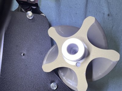
The biggest thing was that there was a bunch of weird stuff with one of the rotors: missing a spline/knurl, runout, a cross threaded thing. They ended up replacing both of my gen 1 rotors with a pair of gen 2 rotors, then only charged me for one new rotor.

Jon bond called me and spent like 30 minutes explaining all the stuff to me after they had it together. It seems like the unit had been apart before? The invoice summed it up pretty well:

On cleaning and final disassembly of the supercharger- the input shaft has no splined surface to retain the 3 pin hub. Spline the input shaft to avoid the 3 pin hub slipping in place. If the hub does slip, we would recommend replacing the drive snout.

We coated the 3 and 5 lobe rotors. Upon assembly, the 5 lobe rotor had runout when assembled. Check runout. Runout was caused by a bent rotor shaft bolt. We went to extract rotor shaft stud to replace it, since it seemed bent, and found the rotor stud crossthreaded in the rotor housing. In the past, someone had extracted the rotor stud, and then re-inserted it crossthreaded. This was causing the runout. There should never have been a reason to remove this stud in a normal service procedure. We cannot repair this damage to the rotor.

We do not have this generation of rotor as they are discontinued. We installed a matching G2 1600A rotor set, drive gears, and 3 pin hub and traded customer’s 3 lobe rotor, gear, and 3 pin hub. We could have required the customer to purchase an entire rotor pack at $1999.99, but we did our best to minimize this unknown damage. There would have been no way of knowning about this damage, as we do not turn assemblies when they come in as they are full of dirt or debris.

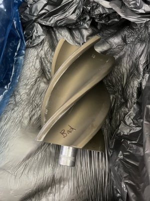
Cool. They sent me all the old parts including the old 5 lobe rotor, it’s a pretty neat part:

BC436541-BD69-4278-A824-815922982073.jpeg

I think the cross threaded stud went in here:

8F03176C-3CD9-4B1D-97B1-7618790BE17A.jpeg

I was hoping for more efficiency or something with the new rotors. But nope, they told me the benefit of the gen 2 rotors and gear case bits is better reliability. I guess this blower style went through like 6 revisions, entirely for the sake of reliability. This blower was the original first gen 1600A, but now it has some of those reliability improvements (e.g. carbon coupler). It should last 60-80k miles easy they said. The car has 135k on it now, so I’d be looking at a rebuild around 195k - 215k. By then I’ll have that K48 V8 thing in this car anyway….
 
Back
Top